X3D Programmable Shaders
Gonçalo Nuno Moutinho de Carvalho, University of Teesside c3099023@tees.ac.uk
Justin Couch, Yumetech justin@vlc.com.au
Tony Gill, CSIRO tony.gill@csiro.au
Tony Parisi, Media Machines tparisi@mediamachines.com
November 21, 2003
This proposal describes a method of incorporating hardware-based programmable shaders into X3D. It is being submitted for consideration by the X3D Programmable Shaders Working Group as a possible basis for the official Web3D Programmable Shaders component being developed by the group. The authors acknowledge that there are open issues and limitations in this design and would encourage input and cooperation from other members of the working group to improve it in order to create the most rugged and general-purpose design possible.
The method synthesizes designs originally proposed by the authors under two separate proposals. Justin Couch and Tony Parisi’s proposal may be found here and Gonçalo Nuno Moutinho de Carvalho’s here. The work described in the Couch-Parisi proposal was initially prototyped by Media Machines in partnership with CSIRO, and it was first demonstrated publicly at the SIGGRAPH conference in San Diego on July 29, 2003.Gonçalo Nuno Moutinho de Carvalho's shaders prototype definition was developed at the Glasgow School of Art. They formed part of a X3D player dubbed RealightXP™ and were first demonstrated in public at the London IMAX as part of the AVNET launching event, in November 2002. More recently they were also the topic of a presentation at the SIGGRAPH 2003 Web Graphics program, and their use was also referenced in a CNN news bulletin.
The examples included herein, with the exception of the environment map prefiltering, were developed by Tony Gill of CSIRO. The environment map prefiltering example was originally developed by Gonçalo Nuno Moutinho de Carvalho; Tony Gill converted that example to use the nodes contained in this proposal. All figures were rendered using a customized version of the Media Machines' Flux™ player on Windows with the NVIDIA's Cg shader language libraries.
This method is based on three ideas:
Shaders are treated as Appearance properties, located in the scene graph wherever a Material or Texture may be used;
Shaders behave much like Scripts, in the sense that have user-definable fields and a binding to the underlying shader hardware programming language that provides the implementation;
Multiple shader effects may be applied to single object using multiple rendering passes and/or stages.
Note that because shaders are treated like other appearance properties, they are not applied to entire groups of objects or inherited as with lights. Reuse of shaders requires DEF/USE as with any other appearance property. This was done for consistency with the X3D appearance model described in the 12, Shape component.
The design requires five new node types to be added to X3D.
The abstract base type, X3DShaderNode, is a marker type that incorporates the base functionality of X3DScriptNode enabling the creation of a shader with user-defined fields and a binding to the underlying shader hardware programming language.
The concrete shader node types FragmentShader and VertexShader inherit from X3DShaderNode and implement fragment (pixel) and vertex shaders, respectively. The interface definitions for these node types are identical. However, fragment and vertex shaders are used in distinct parts of the rendering pipeline, thus the use of two distinct node types to represent them.
A new class of appearance node, ShaderAppearance, is employed to attach fragment and vertex shaders to specific renderable objects in the scene graph. ShaderAppearance inherits from X3DAppearanceNode and may be used in the scene graph as the value of the appearance field of a Shape node.
Multiple shader effects may be applied to single object using MultiShaderAppearance, another appearance node that groups ShaderAppearance nodes and defines operations for combining their output in multiple stages in the hardware or via successive rendering passes in software.
A variety of special-purpose programming languages have emerged to implement hardware-assisted high-level procedural shaders. Browsers are not required to support any specific languages. However, support for the languages listed in Table 2 is recommended:
|
Language |
Reference |
|
OpenGL Shader Language (glsl) |
|
|
Microsoft High-Level Shader Language (HLSL) |
|
|
NVIDIA Cg Shader Language |
The shader node's url field shall allow for both inline scripting and script reference via a URL. The MIME-type of the returned data defines the language type. Additionally, instructions can be included in-line using the shader language protocols defined in Table 3.
|
Language |
Protocol |
|
OpenGL Shader Language (GLSL) |
“glsl:” |
|
Microsoft High-Level Shader Language (HLSL) |
“hlsl:” |
|
NVIDIA Cg Shader Language |
“cg:” |
Issue: not all hardware shader languages have a defined MIME type at this point in time; we may have to register this with IETF ourselves if the vendors/standards bodies have not at the time we standardize.
For example, the following Script node has one field named shininess and three different URL values specified in the url field: Java, ECMAScript, and inline ECMAScript:
VertexShader {
 field SFFloat shininess
 url [ “
http://foo.com/fooBar.hlsl”,
       “cg: void main(in float4 position : POSITION, ...”
 ]
}
In the above example when a shininess event is received by the shader node, its value is updated for use by the shader program the next time the object is rendered. Which shader program is used by the browser is determined by the url field. The HLSL language shader bytecode is the first choice and the inline Cg code the second choice. A description of order of preference for multiple valued URL fields may be found in the X3D Specification, 9.2.1, URLs.
Many of the data types in each language binding map with the existing X3D field types. It is necessary to define a mapping of the data types for each language binding to the field types in X3D. For example, Table 4 defines the mappings for X3D field types to NVIDIA’s Cg. Similar tables can be provided for HLSL and GLSL.
|
X3D |
Cg |
|
SFRotation |
float4 |
|
SFVec3f |
float3 |
|
SFColor |
float3 |
|
SFVec2f |
float2 |
|
SFTime |
float |
|
SFBool |
int |
|
SFImage |
array of ints |
|
SFNode |
for an X3DTextureNode, maps to the appropriate sampler{1D, 2D, 3D, CUBE, SHADOW, RECT}. No mapping for other node types. |
|
SFString |
no mapping |
X3DShaderNode : X3DScriptNode {
 MFString  [in,out]  url          []
 SFBool    []        mustEvaluate FALSE
 MFString  [in, out] paramName    []
 MFString  [in, out] paramType    []

 # And any number of:
 fieldType []        fieldName
 fieldType [in]      fieldName
 fieldType [out]     fieldName
 fieldType [in,out]  fieldName
}
The X3DShaderNode abstract type is the base for all vertex and fragment shader node types. Each shader node has associated shader programming language code (hereinafter referred to as the "shader"), referenced by the url field, that is executed to carry out the shader node's function. Details on the url field can be found in the X3D Specification, 9.2.1, URLs.
Browsers are not required to support any specific language. Detailed information on shader languages is described in 1.3 Shader languages.
The shader is able to receive and process events that are sent to it. Each event that can be received shall be declared in the shader node using the same syntax as is used in a prototype definition:
inputOnly type name
The type can be any of the standard X3D fields (as defined in the X3D specification , 5. Field type reference). Name shall be an identifier that is unique for this shader node.
If the shader node's mustEvaluate field is FALSE, the browser may delay sending input events to the shader until its outputs are needed by the browser. If the mustEvaluate field is TRUE, the browser shall send input events to the script as soon as possible, regardless of whether the outputs are needed.
The paramName and paramType fields define a mapping between parameters of the underlyling shader program and global state within the X3D browser. By default, each field defined in the shader node is mapped to a parameter of the same name and data type in the shader program. However, shader programs may require values that are not explicitly defined in the shader node's interface but maintained as rendering state within the browser, such as the world space position of one of the active lights. Values in the paramName field specify the names of the shader program parameter names to which these built-in values are applied. The paramType field allows the author to specify the built-in values by using keywords as defined in Table 5. In GL2 some of these values are natively available inside the shader and can be omitted. Each element of the paramType field is used to define the builtin type of the value to be supplied in the shader program parameter as named in the corresponding element of the paramName field. The paramType and paramName fields must contain exactly the same number of elements.
[GL2 refers to any OpenGL implementation that implements the OpenGL Shading Language and/or the ARB extensions for a native shading language.]
|
Keyword |
Data Type |
Semantic |
API |
|
LIGHTWPOSx |
32-bit single precision 3x1 vector |
World-space position of light x[0..7] |
D3D and GL2 |
|
LIGHTWORIENTx |
32-bit single precision 4x4 matrix |
World-space orientation of light x[0..7] |
D3D and GL2 |
|
LIGHTMPOSx |
32-bit single precision 3x1 vector |
Model-space position of light x[0..7] |
D3D and GL2 |
|
LIGHTMORIENTx |
32-bit single precision 4x4 matrix |
Model-space orientation of light x[0..7] |
D3D and GL2 |
|
LIGHTSTATE |
32-bit integer |
Bit vector of on/off light states [0..7] |
GL2 |
|
WORLDMATRIX |
32-bit single precision 4x4 matrix |
World-space matrix |
D3D |
|
VIEWMATRIX |
32-bit single precision 4x4 matrix |
View-space matrix |
D3D |
|
PROJMATRIX |
32-bit single precision 4x4 matrix |
Projection matrix |
D3D |
|
WVPMATRIX |
32-bit single precision 4x4 matrix |
Concatenation of world, view and projection matrices |
D3D |
|
NORMALMATRIX |
32-bit single precision 4x4 matrix |
Matrix for transformation of normals |
D3D |
FragmentShader : X3DShaderNode {
 MFString  [in,out] url []
 # And any number of:
 fieldType []       fieldName
 fieldType [in]     fieldName
 fieldType [out]    fieldName
 fieldType [in,out] fieldName
}
The FragmentShader node implements a fragment (pixel) shader for per-pixel effects. FragmentShader nodes may only appear as values of the fragmentShader field of the ShaderAppearance node. Details on the FragmentShader node’s fields are described in 2.1, X3DShaderNode.
MultiShaderAppearance : X3DAppearanceNode {
 SFNode [in,out] fillProperties   NULL [FillProperties]
 SFNode [in,out] lineProperties   NULL [LineProperties]
 SFNode [in,out] material         NULL [X3DMaterialNode]
 MFNode [in,out] shaderAppearance []   [ShaderAppearance]
 MFNode [in,out] shaderOp         []   [DrawOp]
 SFNode [in,out] texture          NULL [X3DTextureNode]
 SFNode [in,out] textureTransform NULL [X3DTextureTransformNode]
}
MultiShaderAppearance is an extended X3DAppearanceNode that combines multiple shader effects on a single object either via multiple rendering stages in the hardware or several rendering passes in software. MultiShaderAppearance groups ShaderAppearance nodes and defines operations for combining their output in multiple stages in the hardware or via successive rendering passes.
MultiShaderAppearance nodes may be used in the scene graph wherever regular Appearance nodes are used, i.e. as the appearance field of a Shape node. Note that by combining an appropriate set of shaders properly, MultiShaderAppearance can be used to mimic the fixed-function pipeline.
The shaderAppearance field may contain zero or more nodes of type ShaderAppearance. If more than one of these nodes is present, then MultiShaderAppearance describes a multipass algorithm, with each pass controlled by a different ShaderAppearance.
The drawOps field contains nodes of type DrawOp, kindly made available by Holger Grahn, and defines how each of the fragments is composited. The number of nodes in this field must be equal or greater to the number of nodes in the shaderAppearance field. The player will return the pipeline to the default state as defined by the X3D base specification.
[Note the dependency on DrawOp. I don’t think this node should be defined in this component but rather in a new X3D Compositing component where we define the layers model. We would simply reference that component. For now we’ll have to deal with it in this proposal somehow.]
ShaderAppearance : X3DAppearanceNode {
 SFNode [in,out] fillProperties   NULL [FillProperties]
 SFNode [in,out] fragmentShader   NULL [FragmentShader]
 SFNode [in,out] lineProperties   NULL [LineProperties]
 SFNode [in,out] material         NULL [X3DMaterialNode]
 SFNode [in,out] texture          NULL [X3DTextureNode]
 SFNode [in,out] textureTransform NULL [X3DTextureTransformNode]
 SFNode [in,out] vertexShader     NULL [VertexShader]
}
ShaderAppearance is an extended X3DAppearanceNode that has associated vertex and fragment shader fields in addition to all of the base appearance properties. ShaderAppearance nodes may be used in the scene graph wherever regular Appearance nodes are used, that is as the appearance field of a Shape node.
The inherited appearance fields of ShaderAppearance (that is fillProperties, lineProperties, material, texture and textureTransform) are used to provide fallbacks in case the fragment shader program node is not available or is implemented in a shader programming language not supported by the browser. If the vertex shader is not available or not supported, geometry will be interpreted according to the rules defined in the base X3D specification.
VertexShader : X3DShaderNode {
 MFString  [in,out] url []
 # And any number of:
 fieldType []       fieldName
 fieldType [in]     fieldName
 fieldType [out]    fieldName
 fieldType [in,out] fieldName
}
The VertexShader node implements a vertex shader for per-vertex effects such as morphing and shading. VertexShader nodes may only appear as values of the vertexShader field of the ShaderAppearance node. Details on the VertexShader node’s fields are described in 2.1, X3DShaderNode.
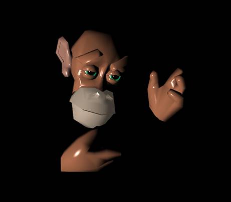
This example adds flair to the old Protozoa VRML model, “Fred the Space Monkey.” The shading used in the Fred example provides the user with a monkey that looks like it is made from plastic, which adds to his already comical appeal. The lighting model employed makes it possible to create more visually appealing characters without having to increase the complexity of the geometry, resulting in smoother animations. The example highlights the following technical aspect of programmable shaders:
1. Phong (per pixel) shading.
2. Uses a specular and diffuse lighting model only.
The Fred example is depicted in Figure 1.
The example defines vertex and fragment shader nodes programmed in Cg language as follows:
Shape {
 appearance DEF VSkin ShaderAppearance {
 vertexShader DEF VShader01 VertexShader {
  field SFFloat time 0
  url "cg:
 void main(
 in float4 position : POSITION, //in model space
 in float4 normal : NORMAL, //in model space

 //mandatory parameters
 uniform float4x4 modelViewProj, //in Flux (D3D) world space
 uniform float4x4 modelToWorld, //in Flux (D3D) world space
 uniform float4x4 modelToWorldInvTrans, //in Flux (D3D) world space
 uniform float3 cameraPosition, //in Flux (D3D) world space

 //currently only a maximum of 10 of these parameters are supported
 //there must be a corresponding X3D field for each of these
 uniform float time,

 //output parameters
 out float4 oPosition : POSITION, //in Flux (D3D) world space
 out float3 oObjectPos : TEXCOORD0, //in Flux (D3D) world space
 out float3 oNormal : TEXCOORD1 //in Flux (D3D) world space
 )
 {
 oPosition = mul(modelViewProj, position);

 //transform the vertex position and normal into Flux (D3D) World Space:
 oObjectPos = mul(modelToWorld, position).xyz;
 oNormal = mul(modelToWorldInvTrans, normal).xyz;
 }"
 }
 fragmentShader DEF FShader01 FragmentShader {
  field SFColor baseColor 0.673469 0.420254 0.297996
  field SFVec3f lightPosition -10 0 10
  field SFVec3f camPosition 0 0 10
  url "cg:
 void main(
 in float4 position : TEXCOORD0, //in Flux (D3D) world space
 in float3 normal : TEXCOORD1, //in Flux (D3D) world space

 uniform float3 cameraPosition, //mandatory in Flux (D3D) Flux world space

 uniform float3 baseColor,
 uniform float3 lightPosition, //defined in x3d world space
 uniform float3 camPosition, //defined in x3d world space

 out float4 oColor : COLOR)
 {
 float3 lightColor = float3(1.0f, 1.0f, 1.0f);

 float3 P = position.xyz;
 float3 N = normalize(normal);

 //get lightPosition into Flux space
 lightPosition.z = -lightPosition.z;

 //compute the diffuseColor value, assume lightColor is white
 float3 L = normalize(lightPosition - P);
 float diffuseLight = max(dot(N, L), 0);
 float3 diffuse = baseColor * lightColor * diffuseLight;

 //compute the specular term:
 //assume specular color and light color are white
 float3 V = normalize(cameraPosition - P);
 float3 H = normalize(L + V);
 float specularLight = pow(max(dot(N, H), 0), 256);
 if(diffuseLight <= 0)
 specularLight = 0;

 float3 specular = lightColor * specularLight;
 oColor.xyz = (diffuse + specular);
 oColor.w = 1;
 }
 "}
 }
}
The full source file for this example may be found here.
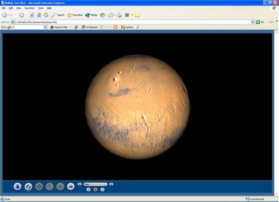
Bump mapping simulates bumpiness in a surface without distorting the surface's geometry. It is achieved by perturbing the surface's normal using a per-pixel normal encoded within a texture map. The resultant normal is used to compute the final color of each fragment.
An example of bump mapping using the planet Mars is shown in Figure 2.
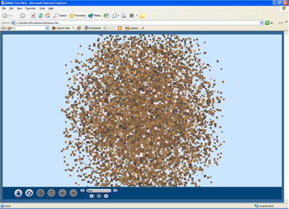
In this example each particle is a member of a PointSet that contains 10000 points, and has its displacement and final size calculated dynamically by the vertex shader. A similar particle effect created using a PositionInterpolator would require a very large file since a set of positions for each of the 10000 particles would have to be defined, and each point's size would be fixed and determined by the X3D player.
An example of the particle system shader is shown in Figure 3.
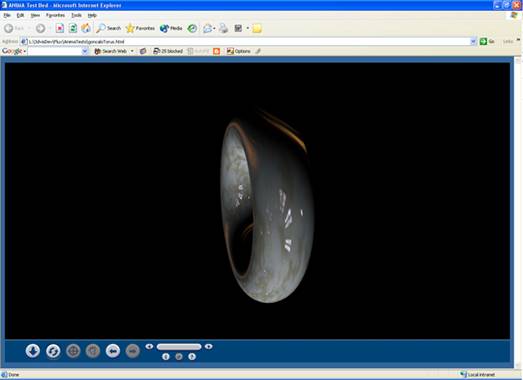
Environment maps can be used to compute a mirror reflection term that can be added to local illumination terms for a given lighting model [Olano et.al 2001]. Without prefiltering, an environment map can only model polished metallic surfaces, since the Fresnel term (the reflectivity of a material off a polished surface in the mirror direction of the incoming light) is almost equal to one. For non-metallic surfaces, mirror reflections must be weighted by the Fresnel term. If we hold the outgoing radiance in the environment map instead of holding the reflected environment, then we have a prefiltered environment map.
For this example, we wish to obtain a transparent coating on the surface of a torus. The environment map use for this example is pre-multiplied by a texture map containing a Fresnel map describing a optical density of 50. The final effect is accomplished by using the Fresnel term to perform a blend between the diffuse and reflection terms. The final effect is typical of car paint.
Figure 4 shows a torus with a transparent coating.
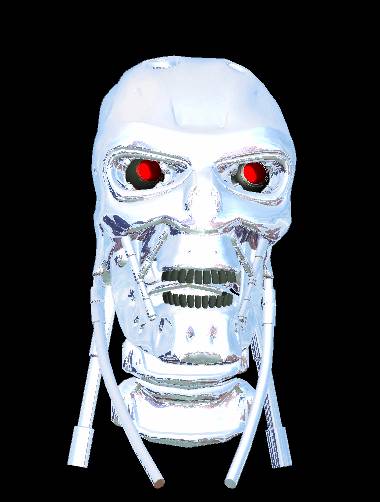
The appearance of a shiny metallic object is defined by its surrounding environment. An effect known as environment mapping can be used to make objects look as though they are reflecting the environment in which they are located. Such effects provide the user with a more visually realistic scene and a more enjoyable experience. This example uses environment mapping to render a model Terminator robot by employing the following technical apsects of programmable shaders:
1. Cubic environment mapping blended with a diffuse colour component to get the silver effect.
2. The final effect will be vastly improved when the surrounding environment is rendered.
The Terminator example is depicted in Figure 5.
The full source file for this example may be found here.
A glass effect is achieved by simulating the refraction of light using a technique known as cubic environment mapping [Greene 1986]. Using this technique the surrounding environment is captured within a texture known as a cube texture. For each pixel on a chess piece the refracted vector incident with that pixel is computed in the vertex shader and passed to the fragment shader. The final colour of the pixel on the chess piece is computed in the fragment shader and is the value of the cube texture where it intersects the refracted eye vector.
Figure 6 shows chess pieces with the refraction environment mapping applied so they appear they are made from glass.
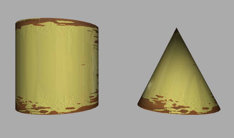
As metal ages it tends to rust. This example, based on NVIDIA’s time machine demo, illustrates how shaders can be used in X3D to achieve the rust effect. The scene is animated so that as time increases the primitives are made to look as though they are falling into disrepair by using a combination of effects executed using the graphics hardware. The example highlights the following technical aspect of shaders in X3D:
1. The primitives are animated using ROUTEs so that the objects rust as time passes similar to the NVIDIA's time machine demo.
2. Environment mapping is employed to make the primitives look reflective
3. Bump mapping is used to increase the noise on the surface as the primitives age.
4. The rust is a simple 2D texture map with the texture coordinates computed dynamically in order to increase the amount of rust that appears as time increases.
5. The rust, bump, and environment maps are blended with diffuse and speculat lighting calculations in the fragment shader to give the rust its final look.
The rusted primitives example is depicted in Figure 7.
The full source file for this example may be found here.
Many rendering effects, for example, bump mapping, make use of additional per-vertex information such as tangents and secondary tangents (binormals). X3D has no native way of specifying such data. Given the current base specification an author can use the following guidelines:
Reuse unused fields in the geometry nodes, such as Color;
Provide a texture in which such vector information is encoded as color values, in the same vein as normal maps;
Define a script where an MFVec3f exists with such information and ROUTE it to a MFVec3f field in the appropriate shader node;
Pass all the information to the shader as an MFVec3f value.
It is also worth mentioning that many traditional shader effects such as procedural textures, make extensive use
of Perlin noise functions. The common way of representing such a function in programmable hardware is by means of a 3D texture. Unfortunately this texture cannot be represented as a 3D texture using the current base specification. Furthermore, texture coordinates in X3D are of type SFVec2f complicating matters even further. A workaround is to specify an MFVec3f to the shader and do the indexing computation and evaluation of the function inside the shader. Both of these examples could be easily represented in X3D with the introduction of support for 3D textures, including the use of the SFVec3f type as a texture coordinate value.
The overall effect of a programmable shader can be returned in a texture, allowing for return values from shaders. Procedural textures can be generated and returned and then bound to another shader allowing for some dynamic and interesting effects. Unfortunately, X3D lacks the support to render to an arbitrary buffer. It is the authors' opinion that this would be a useful addition to the base specification.
Another open issue relates to the deformation of vertices done by a vertex shader and in particular to the bounding volume (internally a browser does not need to use only bounding boxes. It can use a combination of bounding spheres, object-oriented boxes, etc.) that encloses such a piece of geometry. Since the vertices are changing positions the bounding volume also changes. The browser can make use of bounding volume information for efficiency purposes while rendering and computing intersections, and because the vertices are being transformed inside the shader, there is the potential for incorrect results if this information is not being passed back to the browser. Authors can use the following guidelines:
Specify in the bboxVec and bboxSize fields the maximum possible bounding box in the enclosing Shape node.
Duplicate in a Script node the computation being performed by the vertex shader and ROUTE it to the appropriate fields in the enclosing Grouping and/or Shape node.
A more intrusive solution would be to introduce in ShaderAppearance a proxy node to be used for intersections. If the proxy is NULL, the Shape geometry is used, otherwise the proxy is used.
Shading languages cannot be used interchangibly. The results are undefined if a vertex shader is specified using a language that is different from the one used to specify the fragment shader.
Finally, not all hardware shader languages have a defined MIME type at this point in time; we may have to register this with IETF ourselves if the vendors/standards bodies have not at the time we standardize (see note after Table 3)
Olano, M., Hart, John C., Heidrich W, and McCool, M. 2002. Real-Time Shading. A. K. Peters,
Greene, N. 1986. Environment Mapping and Other Applications of World Projections. IEEE Computer Graphics and Applications 6, 11, 21-29.